The multimeter can insert automatic measurement settling delays. These delays are adequate for resistance measurements with less than 200 pF of combined cable and device capacitance. This is particularly important when measuring resistances above 100 kΩ. Settling due to RC time constant effects can be quite long. Some precision resistors and multi–function calibrators use large parallel capacitors (1000 pF to 0.1 µF) with high resistor values to filter out noise currents injected by their internal circuitry. Non–ideal capacitances in cables and other devices may have much longer settling times than expected just by RC time constants due to dielectric absorption (soak) effects. Errors are measured when settling after the initial connection and after a range change.
In the AC voltage function, the input of the multimeter appears as a 1 MΩ resistance in parallel with 100 pF of capacitance. The cabling that you use to connect signals to the multimeter also adds capacitance and loading. The table below shows the multimeter's approximate input resistance at various frequencies.
| Input Frequency | Input Resistance (kΩ) |
|---|---|
| 100 Hz | 941 |
| 1 kHz | 614 |
| 10 kHz | 137 |
| 100 kHz | 15.7 |
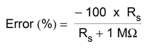
For low frequencies, the loading error is:
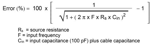
At high frequencies, the additional loading error is:
You can make the most accurate AC measurements when the multimeter is at or near the full scale of the selected range. Autoranging occurs at 10% (down–range) and 120% (up–range) of full scale. This enables you to measure some inputs at full scale on one range and 10% of full scale on the next higher range. In general, the accuracy is better on the lower range; for the highest accuracy, select the lowest manual range possible for the measurement.
If you apply more than 300 Vrms, self–heating occurs in the multimeter's internal signal–conditioning components. These errors are included in the multimeter's specifications. Temperature changes inside the multimeter due to self–heating may cause additional error on other AC voltage ranges. The additional error is less than 0.02% and dissipates in a few minutes.
Burden voltage errors, which apply to DC current, also apply to AC current measurements. However, the burden voltage for AC current is larger due to the multimeter's series inductance and your measurement connections. The burden voltage increases as the input frequency increases. Some circuits may oscillate when performing current measurements due to the multimeter's series inductance and your measurement connections.
AC voltage measurements less than 100 mV are especially susceptible to errors introduced by extraneous noise sources. An exposed test lead acts as an antenna and a properly functioning DMM will measure the signals received. The entire measurement path, including the power line, act as a loop antenna. Circulating currents in the loop create error voltages across any impedances in series with the DMM's input. Therefore, you should apply low–level AC voltages to the DMM through shielded cables, with the shield connected to the input LO terminal.
Connect the DMM and the AC source to the same electrical outlet whenever possible. You should also minimize the area of any ground loops that cannot be avoided. A high–impedance source is more susceptible to noise pickup than a low–impedance source. You can reduce the high–frequency impedance of a source by placing a capacitor in parallel with the DMM's input terminals. You may have to experiment to determine the correct capacitor for your application.
Most extraneous noise is not correlated with the input signal. You can determine the error as shown below.
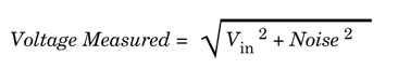
Correlated noise, while rare, is especially detrimental because it always adds directly to the input signal. Measuring a low–level signal with the same frequency as the local power line is a common situation that is prone to this error.
Errors are generated when the multimeter's input LO terminal is driven with an AC voltage relative to earth. The most common situation where unnecessary common mode voltages are created is when the output of an AC calibrator is connected to the multimeter "backwards." Ideally, a multimeter reads the same regardless of how the source is connected. Both source and multimeter effects can degrade this ideal situation. Because of the capacitance between the input LO terminal and earth (approximately 200 pF), the source will experience different loading depending on how the input is applied. The magnitude of the error is dependent upon the source's response to this loading.
The DMM's measurement circuitry, while extensively shielded, responds differently in the backward input case due to slight differences in stray capacitance to earth. The DMM's errors are greatest for high–voltage, high–frequency inputs. Typically, the DMM exhibits about 0.06% additional error for a 100 V, 100 kHz reverse input. You can use the grounding techniques described for DC common mode problems to minimize AC common mode voltages.
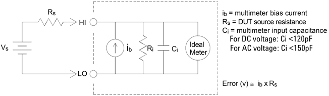
The DMM's input capacitance will "charge up" due to input bias currents when the terminals are open–circuited (if the input resistance is >10 GΩ). The DMM's measuring circuitry exhibits approximately 30pA of input bias current for ambient temperatures from 0 to 30 °C. Bias current doubles for every 8 °C change in ambient temperature above 30 °C. This current generates small voltage offsets dependent upon the source resistance of the DUT. This effect becomes evident for a source resistance of greater than 100 kΩ, or when the DMM's operating temperature is significantly greater than 30 °C.
Both 3A and 10A terminals are available for AC and DC current measurements. If signals are applied to terminals not being used for the current measurement, measurement errors may occur. The unused terminals are protected but the additional signals may interfere with current measurements. For example, applying inputs to the 3A terminals while making measurements on the 10A terminals will typically cause errors.
Unnecessary signals applied to the Hi and Lo Sense terminals can also cause errors. AC or DC voltages above 15 volts peak on the sense terminals are likely to cause measurement errors.